Terminal block management: Multi-level terminal strips and the Terminal Strip Editor
Note: access part 1 of this tutorial here and part 2 here.
Autodesk’s Nathan Eliason hosted a webcast last week that focused on AutoCAD Electrical’s ability to insert, track, and manage terminal blocks / terminal strips in a project drawing set. I helped put the demo together and was responsible for real-time Q & A support while Nathan was “on stage”.
Also thanks to Doug McAlexander for some of the images and samples.
Part 3
Note: this posting is a brief summary of what Nathan covered in the last 15 minutes of the hour-long webcast. This part deals with using the Terminal Strip Editor tool to assign groups of schematic terminals to triple-level terminal blocks on the panel layout representation.
Okay, picking up from where we left off in part 2 of the tutorial… now let’s do TB-2 for the remaining three 3-phase motors in our design.
Let’s target this piece of DIN rail to hold these terminals. And as a challenge, let’s go with triple-level terminals this time, one terminal to take care of each motor.
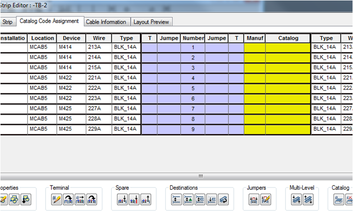
Launch Terminal Strip “Editor” as before but now select “TB-2” from the opening dialog.
Then select “Catalog Code Assignment” tab. We’re ready to assign a catalog part number.
Let’s go with a triple-deck terminal, one terminal block to take care of the 3-phase wire connections for each of the three motors.
Highlight the first terminal row in the dialog list. We’re going to flip this into a triple-level terminal and run all three motor wires through this one terminal block.
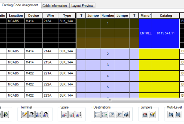
Select ENTRELEC again, “MULTI-LEVEL”, and make the catalog selection shown above.
Changing this terminal to be a triple-level terminal expands this entry.
So, all we did is select a part number that is for a triple-level terminal and the Terminal Strip Editor expands the grid to show the extra two unused terminal positions.
Wait a minute… how does the Terminal Strip Editor know that this particular Entrelec part number is supposed to be a triple-level terminal? Excellent question… this is all set up in terminal property tables in the AutoCAD Electrical catalog lookup database file (below).
Above is the entry for this Entrelec terminal. It is flagged as “3” levels deep.
Back to the demo…
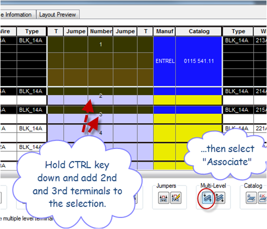
Next we highlight it and the next two terminals (the other two wires for this first motor). We want to include these two wires as the 2nd and 3rd levels of the first 3-level terminal.
Select terminals 2 and 3 using the CTRL key and click the “Associate” button under the “Multi-Level” category of the menu.
Hint: The graphic at the left indicates a multilevel terminal with three levels but only one level is in use at the moment.
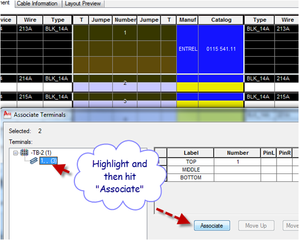
Next highlight the selection on the left as shown. Hit the “Associate” button. This will move the two highlighted entries in with the main 3-level terminal.
The first three single terminals are now combined into a single 3-level terminal.
Repeat the process for the other two sets of 3-terminals. Use the “Copy Catalog Number” and “Paste Catalog Number” commands to copy the first terminal’s part number assignment down to terminals 4 and 7, converting each of them to a 3-level terminal.
Selecting “Layout Preview” to check on progress, we see our three triple-level terminals now in place and the other unused terminals now shown spare.
At this point we can go back in to the Terminal Strip tab, highlight one of the spares in each group, right-click, and select “Spare” –> “Delete”.
We could convert the other spares to separator plates, end plates, of end barriers, as-needed, by clicking the “Catalog Code Assignment” tab and looking up the appropriate part numbers.
Hint: Pretty much everything in the icon menu at the bottom of the Terminal Strip Editor dialog can be accomplished from a context-driven right-click menu. Just select a terminal and right-click to see the menu options.
There it is. The two terminal strips inserted into the panel layout and linked back to the schematics.
Now let’s do some clean-up on the TB-2. We need to add in an “End Stop” accessory at the top and the bottom of this TB-2 terminal strip. Re-launch Terminal Strip Editor and select TB-2.
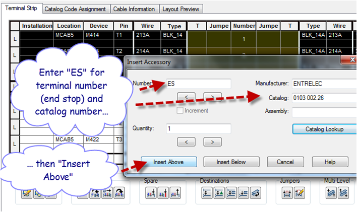
Add an End Stop before the very first terminal. To do this, highlight the first terminal in the editor dialog. Then right-click on the highlighted entry and pick “Accessories” and then “Insert”.
The “terminal number” cannot be left blank for accessory items, even though this is not really a terminal. Just enter “ES” for its terminal number.
Enter “ENTRELEC” and part number “0103 002.26” for the “End Stop” … or do “Catalog Lookup” to select the end stop accessory item.
Exit this sub-dialog by hitting the “Insert Above” button. Follow same process to insert the second End Stop at the bottom of the terminal strip.
Selecting “Layout Preview” we see the end stop accessory items added in to our TB-2 terminal strip. Hit “Rebuild” button to cause the existing terminal strip layout to rebuild and now show the end stops added at each end of the strip.
This Entrelec triple-level terminal symbol has each pair of terminals and associated wire connection data color-coded. This suggestion came from Doug McAlexander to make it easier to visually associate each of the three wire number pairs with its color-coded terminal number.
These terminal symbols are just regular AutoCAD blocks with attributes. You can adjust as you see fit. The default root folder for footprint symbols for your project is defined in the active project.
Right-click on the project name in the AcadE “Project Manager” dialog and select “Properties…” to display the dialog shown above.








good guide (all 3 together).
I have 1 little thing to add tho. When you add an asseccory u mentioned it can not be left blank.
On the point of insertion it needs to be numbered / named. But you can get it inserted without numbering / naming it.
Here is how to :
Insert asseccory just as you mentioned and insert (either above or below)
Now right-click on the inserted terminal and go to “terminal” -> Edit. now remove the name / number and it is a blank end/stop terminal.
Best regards,
Vincent Mulder
Comment by Vincent Mulder — February 8, 2011 @ 10:13 am