Autodesk’s Nathan Eliason hosted a webcast earlier today that focused on AutoCAD Electrical’s ability to use Excel to edit its drawing sets. I helped put the demo together and was responsible for real-time Q & A support while Nathan was “on stage”.
This posting is a brief summary of what Nathan covered in the first part of the hour-long webcast – using Excel to quickly revise a copied project. It might serve as a simple overview / tutorial of this AutoCAD Electrical feature.
(NOTE: 100+ other AutoCAD Electrical utilities indexed here.)
Re-cycling a Copied Project – Using Excel to Re-tag/Re-number/Re-assign
Let’s stretch our imaginations today. Let’s pretend that the economy is starting to pick back up.
Word coming down from corporate headquarters is that we need to add another production line. This will basically be a copy of the one we designed with AutoCAD Electrical a couple years ago. We’re happy campers.
To speed things up, we just want to re-cycle the existing AutoCAD Electrical project. This means copying it and its drawings to new names. Then, to finish, we need to do some re-tagging components and wire numbers to keep them unique from the original production line. And we’ll probably need to make a few adjustments in catalog part number assignments.
The edits to component tags, wire numbers, and catalog assignments can be eased by using Excel as an editing interface to the copied drawing set.
So in our tutorial today, let’s go through the steps of how to do this. We’ll just use the demo project that ships with AutoCAD Electrical as our “existing” project that we will copy and modify using Excel.
Note: this Excel-editing capability has been in AutoCAD Electrical for many, many releases… it is not limited to the latest ACE 2011 release.
Step 1 – make a copy of the existing “WDDEMO” project and its drawings
You can do this by hand using normal Windows file copy and file rename…
** OR ** – you can just use the Copy Project tool built into AutoCAD Electrical. Let’s use the tool…
1.1 Go to the “Project” portion of the AutoCAD Electrical ribbon.
1.2 Select “Copy” button near the left-hand end of the ribbon
1.3 Select the “Copy Active Project” button
1.4 Enter a unique, new name for the copied project. Let’s call it “WDDEMO_LINE2”.
1.5 Now select all drawings from old project to copy into this new project. The old drawings remain in the old project… we’re just making copies of the “.dwg” files to move into this new project.
Note: is you have even one of the selected drawings open in your AutoCAD session, the Copy Project command will stop right here with an alert dialog. You’ll need to close that drawing or drawings and start over ( ! ).
1.6 Find/Replace to adjust the copied drawing names and hit OK.
Now we’re ready to go. Our old project and drawings are copied and renamed…
… but they remain a carbon-copy of the original project drawing set.
Our new project requires us to edit tags, wire numbers, and make some changes in catalog part number assignments.
We can use some of the editing tools in AutoCAD Electrical, pick and edit. But wouldn’t it be nice to just do these edits from within the comfortable environment of an Excel spreadsheet ?!!
Let’s do it !
Step 2 – Dumping the Project to Excel
So we’re going to use AutoCAD Electrical’s Excel editing interface to adjust tags, wire numbers, and catalog assignments of our copied drawing set.
First step is to dump the project drawing set’s data out to an Excel spreadsheet. Here’s how:
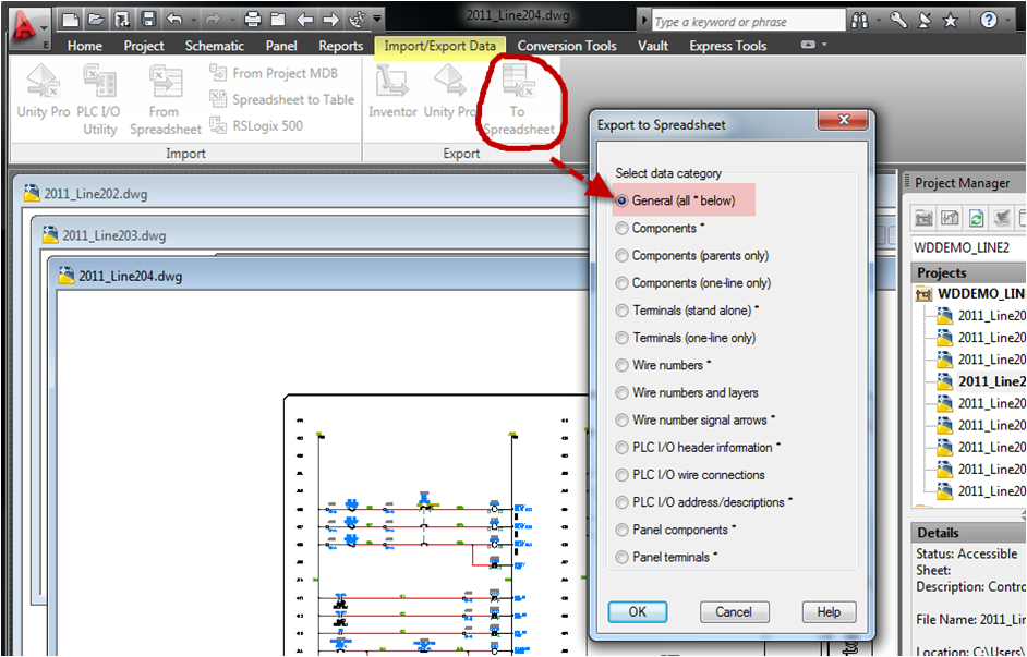
On the ribbon under “Import/Export Data” we select the “To Spreadsheet” tool.
On the dialog that pops open let’s pick the “General” category output. This will dump about eight different categories of project data out to an Excel spreadsheet.
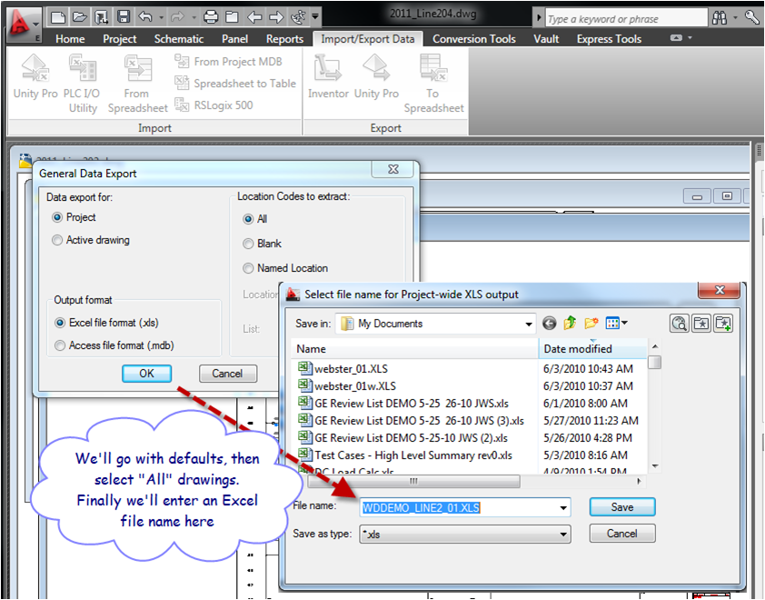
We select “Project” and identify what drawings in the project we want to dump to the Excel spreadsheet (that step’s dialog not shown here).
The last step is to identify a name of the new Excel file. We’ll just let it default to the name that the tool suggests.
Step 3 – Open Excel Spreadsheet, start Editing ( ! )
Important note: AutoCAD Electrical expects to see the spreadsheet field values as “text” and not as “numeric”. If your editing results in some numeric values in some of the cells (text will appear right justified), then AutoCAD Electrical may have difficulty when it tries to read and move edited values back out to update the drawings. Force your edits to be text (one way is to enter pure numeric values with a leading ‘ character, another is by using a macro built into the spreadsheet – see comment at the end of this posting).
We find eight sheets of data, one sheet holding data of a given “category” extracted from the copied drawing set.
For example, the sheet with the “COMP” label (left-hand tab) carries data extract from schematic components and the next sheet, “TERM”, carries data extracted from all schematic terminals found in all drawings of our copied project.
Taking a closer look at the COMP sheet (schematic components).
Each row beginning with the second row gives data extracted from a schematic component block insert instance found in the drawing set.
And the first (top) row is a list of column labels. It gives each column a name that identifies the column’s data type. The data type can be a general category of data or actual block attribute tag-name.
In the example shown above, the component from the schematic carries a dozen or so attributes. Some display as visible text and some are marked invisible. But all are extracted into the component’s row in the COMP table of the spreadsheet.
So the idea here is to now go in the reverse direction… edit values in the spreadsheet and then trigger AutoCAD Electrical to push these edited values back to the component block inserts in the project’s drawings.
Let’s say we do a find/replace in this Excel sheet and manually edit a few other values. Or maybe you get more sophisticated and create some Excel macros to automate making these edits in the spreadsheet.
In any case, whether by manual edits or some cool automation you come up with, when finished, save the spreadsheet.
So, in our example here we’ve highlighted the TAGNAME and the LOC columns and have done several find/replace operations to rename groups of fuse and motor tags and to assign a renamed panel LOC location.
Step 4 – Trigger the Excel –> Drawing update
Now we’re ready to push the data in the updated spreadsheet back out to our AutoCAD Electrical drawing set.
Select the update “From Spreadsheet” tool. We reference our edited Excel spreadsheet.
We select what drawings we want to process (we select the whole project).
Hit OK. And in a few moments our project drawing set is updated per the edited attribute values carried in our spreadsheet.
Results
So, how should this Excel –> AcadE project drawing update work?…
Just picking one example above.
The old project’s tag-ID for this motor starter coil and its child contacts is “M414”. Via our Excel edit, we’ve changed all “M414” instances to “MT-414” for our new project drawing set.
Then running the AutoCAD Electrical update project “From Spreadsheet”, the tag-ID assignment for this motor starter coil on one drawing (the lower left-hand image) and its three power contacts and one auxiliary contact on another drawing should auto-update to match our edited Excel spreadsheet.
Attributes do not have to be visible to update. Attributes marked invisible will update if their values have been changed in the spreadsheet. This means that if our spreadsheet edits include catalog part number assignment changes, those attribute values (normally invisible) will update as well.
Notes
AutoCAD Electrical works best when the spreadsheet edits to be text format and not numeric. A mixture of numeric and text values in the same column of the spreadsheet is especially troublesome. Force all edits to be text. One way is to enter a leading ‘ character for numeric values input into a cell. Another way is to enable the macro content held in the spreadsheet and then run the built-in macro shown below:


Hi Nate.
I have a doubt.
I have to deliver 181 drawings already drawn by me. The problem is that I need to deliver them exploded. No problem, because I use the “special explode”. But i went crazy in the 3º drawing.
I tried with the “project-wide utilities” but with no results.
How could I do it?
Thanks
Ernesto Fraga
Montevideo – Uruguay
Hola Nate
Tengo una duda.
Debo entregar 181 planos ya dibujados por mi. El problema es que me exigen entregarlos explotados. Hasta ahí sin problemas puesto que utilizé el “special explode”. Pero al 3º plano ya me aburrí.
He intentado con el “project-wide utilities” pero no he tenido buenos resulados.
Como lo resuelvo?
Desde ya muchas gracias
Ernesto Fraga
Montevideo – Uruguay
Comment by Ernesto — August 12, 2010 @ 12:23 pm
Is the “ConvToText” macro really built into Excel? I tried running it and it does not seem to exist. I use Excel 2003.
Comment by Scott Gensemer — August 12, 2010 @ 2:15 pm
The “ConvToText” macro is built into the Excel template that AutoCAD Electrical uses when it exports data out of the project and into a spreadsheet. It is not part of “Microsoft Excel”… it is just a macro Autodesk added to its templates for this tool.
Comment by nateholt — August 12, 2010 @ 2:43 pm
[…] Tutorial – Using Excel with AutoCAD Electrical (Part 1) […]
Pingback by Tutorial – Automation of PLC I/O Drawings – AutoCAD Electrical « AutoCAD Electrical Etcetera — September 1, 2010 @ 3:37 pm
[…] Excel with AutoCAD Electrical (Part 3) Tutorial – Using Excel with AutoCAD Electrical (Part 2) Tutorial – Using Excel with AutoCAD Electrical (Part 1) Adding custom option to Insert WBlock Circuit […]
Pingback by Index of AutoCAD Electrical Utilities – April 2006 through August 2010 « AutoCAD Electrical Etcetera — September 1, 2010 @ 3:49 pm
Not sure I understand…, but this tool requires that AutoCAD Electrical is installed and running on your machine. Does this explain the issue?
Comment by nateholt — September 26, 2010 @ 8:04 am
Yep – I found the conversion tool. I thought that it was a macro that came with Excel, not Acad-e. All set. Thanks!
Comment by Scott Gensemer — September 27, 2010 @ 11:09 am